

Hey there! If you're into electronics and DIY projects, you might've wondered how to use a 7 segment LED in a soil moisture sensor circuit. Well, you're in the right place! I'm a supplier of 7 segment LEDs, and I'm gonna walk you through the whole process.
What's a 7 Segment LED?
Before we dive into the soil moisture sensor circuit, let's quickly talk about what a 7 segment LED is. A 7 segment LED is a display device that can show numbers from 0 - 9 and some basic letters. It's made up of seven individual LED segments, usually labeled from a to g, and sometimes an extra decimal point (dp). You can check out different 7 segment LED graphics 7 Segement LED Graphics to get a better idea of how they work.
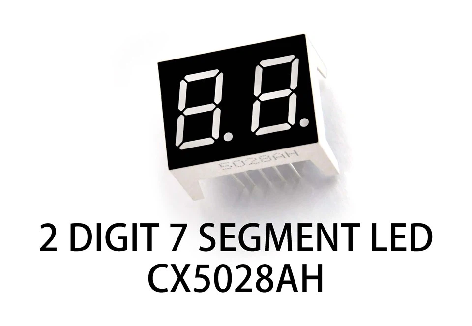
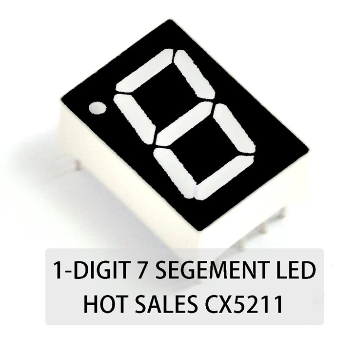
There are different types of 7 segment LEDs, like one-digit and two-digit ones. If you only need to display single-digit numbers, a One-digit 7 Segment LED is a great choice. But if you need to show larger numbers, say two digits, then a Two-digit Seven Segment LED is what you're looking for.
Why Use a 7 Segment LED in a Soil Moisture Sensor Circuit?
Soil moisture sensors are used to measure the amount of water in the soil. This is super important for things like gardening, agriculture, and even some automated irrigation systems. By using a 7 segment LED in the circuit, you can easily display the moisture level in a clear and readable way. Instead of just getting a signal or data on a computer, you can see the actual moisture level right on the display.
Components You'll Need
- 7 Segment LED: As I mentioned, you can choose between one-digit or two-digit LEDs depending on your needs.
- Soil Moisture Sensor: There are many types available in the market. You can pick one based on your budget and the accuracy you require.
- Microcontroller: Something like an Arduino or a Raspberry Pi. These are great for processing the data from the soil moisture sensor and controlling the 7 segment LED.
- Resistors: You'll need some resistors to limit the current flowing through the LEDs and the sensor.
- Breadboard and Jumper Wires: These are used to connect all the components together easily.
Step-by-Step Guide to Building the Circuit
Step 1: Connect the Soil Moisture Sensor
First, connect the soil moisture sensor to the microcontroller. Usually, the sensor has three pins: VCC (power), GND (ground), and SIG (signal). Connect the VCC pin to the 5V output of the microcontroller, the GND pin to the ground of the microcontroller, and the SIG pin to one of the analog input pins (e.g., A0) of the microcontroller.
Step 2: Connect the 7 Segment LED
Next, connect the 7 segment LED to the microcontroller. The 7 segment LED has several pins for the segments (a - g and sometimes dp) and a common pin (either common cathode or common anode). If it's a common cathode LED, connect the common pin to the ground. If it's a common anode LED, connect the common pin to the 5V output. Then, connect each segment pin (a - g and dp) to a digital output pin of the microcontroller through a resistor. The resistor is used to limit the current and protect the LED.
Step 3: Write the Code
Now, it's time to write the code for the microcontroller. The code will do two main things: read the data from the soil moisture sensor and display the corresponding number on the 7 segment LED. Here's a simple example using Arduino:
// Define the pins for the 7 segment LED
const int segmentPins[7] = {2, 3, 4, 5, 6, 7, 8};
// Define the pin for the soil moisture sensor
const int sensorPin = A0;

// Patterns for numbers 0 - 9 on a 7 segment LED (common cathode)
const byte digitPatterns[10] = {
  B00111111, // 0
  B00000110, // 1
  B01011011, // 2
  B01001111, // 3
  B01100110, // 4
  B01101101, // 5
  B01111101, // 6
  B00000111, // 7
  B01111111, // 8
  B01101111  // 9
};

void setup() {
  // Set the segment pins as output
  for (int i = 0; i < 7; i++) {
    pinMode(segmentPins[i], OUTPUT);
  }
}

void loop() {
  // Read the value from the soil moisture sensor
  int sensorValue = analogRead(sensorPin);
  // Map the sensor value to a number from 0 - 9
  int displayNumber = map(sensorValue, 0, 1023, 0, 9);

  // Display the number on the 7 segment LED
  byte pattern = digitPatterns[displayNumber];
  for (int i = 0; i < 7; i++) {
    digitalWrite(segmentPins[i], bitRead(pattern, i));
  }

  delay(100);
}
Step 4: Test the Circuit
Once you've uploaded the code to the microcontroller, it's time to test the circuit. Insert the soil moisture sensor into the soil, and you should see the moisture level displayed on the 7 segment LED. If it's not working, double-check your connections and the code.
Troubleshooting
- No Display on the LED: Check if the power is connected correctly. Make sure the common pin of the LED is connected properly (either to ground or 5V depending on whether it's common cathode or anode). Also, check if the resistors are in the right place and have the correct resistance value.
- Incorrect Numbers Displayed: This could be due to incorrect wiring or a problem with the code. Check the connections between the microcontroller and the LED segments. Also, make sure the digit patterns in the code are correct.
Conclusion
Using a 7 segment LED in a soil moisture sensor circuit is a great way to display the moisture level in a clear and easy-to-read format. It's a fun and educational project that can be useful in many applications. If you're interested in getting high-quality 7 segment LEDs for your projects, feel free to reach out for a purchase negotiation. We have a wide range of options to meet your needs.
References
- Arduino Documentation
- Electronics textbooks on basic circuits and microcontrollers
That's all for today. I hope this guide has been helpful to you. If you have any questions, feel free to leave a comment below.