

An Analog-to-Digital Converter (ADC) is a crucial component in modern electronics, enabling the conversion of continuous analog signals into discrete digital values. When paired with 7 Segment LED Graphics, it becomes a powerful combination for displaying numerical and some alphabetical information in a wide range of applications, from simple household appliances to complex industrial control systems. As a leading supplier of 7 Segement LED Graphics, I'll guide you through the process of using an ADC with 7 Segment LED Graphics, offering insights and practical tips to help you achieve optimal results.
Understanding the Basics
Before delving into the integration of an ADC with 7 Segment LED Graphics, it's essential to understand the fundamental principles of each component.
Analog-to-Digital Converter (ADC)
An ADC is designed to sample an analog signal at regular intervals and convert its amplitude into a digital representation. This digital output can then be processed by a microcontroller or other digital circuits. There are various types of ADCs, including successive approximation ADCs, delta-sigma ADCs, and flash ADCs, each with its own advantages and limitations. The choice of ADC depends on factors such as the required resolution, sampling rate, and cost.
7 Segment LED Graphics
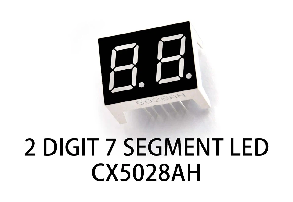
7 Segment LED Graphics consist of seven individual LED segments arranged in a specific pattern, typically in the shape of the digit 8. By selectively lighting up different combinations of these segments, it's possible to display decimal digits from 0 to 9, as well as some alphabetical characters. There are different types of 7 Segment LED displays, including Four-digit 7 Segment LED and Two-digit Seven Segment LED, which can be used to display multiple digits simultaneously.
Connecting the ADC to the 7 Segment LED Graphics
The first step in using an ADC with 7 Segment LED Graphics is to establish the electrical connections between the two components. Here's a general overview of the process:
Step 1: Select the Appropriate ADC and 7 Segment LED Display
Choose an ADC that meets the requirements of your application in terms of resolution, sampling rate, and input voltage range. Similarly, select a 7 Segment LED display that suits your needs in terms of the number of digits, size, and brightness.
Step 2: Connect the ADC Output to the Microcontroller
Most ADCs provide a digital output that can be connected to a microcontroller's input pins. This allows the microcontroller to read the digital values representing the analog input signal. Make sure to follow the ADC's datasheet for the correct pin connections and voltage levels.
Step 3: Connect the Microcontroller to the 7 Segment LED Display
The microcontroller is responsible for processing the digital values from the ADC and controlling the 7 Segment LED display. Connect the microcontroller's output pins to the appropriate input pins of the 7 Segment LED display. You may need to use a decoder or a shift register to simplify the connection and reduce the number of output pins required.
Step 4: Power the Components
Provide the necessary power supply to the ADC, microcontroller, and 7 Segment LED display. Make sure to use a stable power source and follow the recommended voltage levels for each component.
Programming the Microcontroller
Once the hardware connections are established, the next step is to program the microcontroller to read the ADC values and display them on the 7 Segment LED display. Here's a high-level overview of the programming process:
Step 1: Initialize the ADC
Configure the ADC to operate in the desired mode, such as single conversion or continuous conversion. Set the appropriate input channel and resolution.
Step 2: Read the ADC Values
Use the microcontroller's built-in ADC functions or libraries to read the digital values from the ADC. These values represent the amplitude of the analog input signal.
Step 3: Convert the ADC Values to Displayable Format
The digital values from the ADC may need to be converted into a format that can be displayed on the 7 Segment LED display. This may involve scaling the values, converting them to decimal digits, and handling any overflow or underflow conditions.
Step 4: Control the 7 Segment LED Display
Use the microcontroller's output pins to control the individual segments of the 7 Segment LED display. Based on the converted values, selectively light up the appropriate segments to display the desired digits or characters.
Practical Considerations
When using an ADC with 7 Segment LED Graphics, there are several practical considerations to keep in mind:
Noise and Interference
Analog signals are susceptible to noise and interference, which can affect the accuracy of the ADC readings. To minimize these effects, use proper grounding and shielding techniques, and consider using a low-pass filter to remove high-frequency noise.

Refresh Rate
The 7 Segment LED display needs to be refreshed at a regular interval to maintain a stable and flicker-free display. Make sure to adjust the refresh rate based on the type of display and the desired visual quality.
Power Consumption
Both the ADC and the 7 Segment LED display consume power. To minimize power consumption, consider using low-power components and implementing power-saving techniques, such as reducing the brightness of the display or putting the components into sleep mode when not in use.
Conclusion
Using an ADC with 7 Segment LED Graphics is a powerful way to display analog information in a digital format. By following the steps outlined in this blog post and considering the practical considerations, you can successfully integrate these components into your electronic projects. As a trusted supplier of 7 Segement LED Graphics, we offer a wide range of high-quality products to meet your specific needs. If you're interested in purchasing our products or have any questions about using an ADC with 7 Segment LED Graphics, please don't hesitate to contact us for a procurement discussion.
References
- "Analog-to-Digital Converters: Principles, Design, and Applications" by Peter R. Gray and Robert G. Meyer
- "Digital Electronics: Principles and Applications" by Thomas L. Floyd
- "7 Segment LED Display Tutorial" by Electronics Tutorials