Hey there! If you're into electronics and DIY projects, you've probably come across 7 segment LEDs. They're super handy for displaying numbers and simple characters. And if you're using a BASIC Stamp microcontroller, you're in for a treat because it's not that hard to get them working together. As a 7 segment LED supplier, I've seen a lot of folks struggle with this at first. So, I'm gonna walk you through the whole process step by step.
What's a 7 Segment LED Anyway?
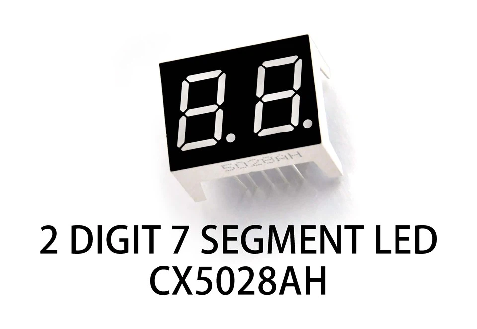
A 7 segment LED is a display made up of seven individual LED segments arranged in a specific pattern. These segments are labeled from A to G, and sometimes there's an extra one for a decimal point (DP). By lighting up different combinations of these segments, you can display numbers from 0 to 9, as well as some letters. It's like a digital version of those old-school calculator displays.
Now, if you're looking for different types of 7 segment LEDs, we've got you covered. Check out 7 Segement LED Graphics to see some cool options. We also have Two-digit Seven Segment LED and Three-digit 7 Segment LED if you need to display multi-digit numbers.
Getting to Know the BASIC Stamp
The BASIC Stamp is a popular microcontroller that's easy to program, even if you're new to electronics. It uses a simplified version of the BASIC programming language, which makes it a great choice for beginners. You can control all sorts of things with it, including 7 segment LEDs.
Parts You'll Need
Before we get started, let's gather the parts we'll need:
- A BASIC Stamp microcontroller (I'm gonna use the BASIC Stamp 2 in this example, but the process is similar for other models).
- A 7 segment LED display. You can choose from single-digit, two-digit, or three-digit displays depending on your needs.
- A breadboard for prototyping.
- Some jumper wires to connect everything.
- A few resistors to limit the current going to the LEDs.
Understanding the Wiring
The first thing you need to do is wire up the 7 segment LED to the BASIC Stamp. The 7 segment LED has 8 pins (7 for the segments and 1 for the decimal point). You'll also need to connect a common pin, which can be either common anode or common cathode. In a common anode display, the positive side of all the LEDs is connected together, and in a common cathode display, the negative side is connected together.
Here's a simple wiring diagram for a single-digit common cathode 7 segment LED:
- Connect pin A of the 7 segment LED to a digital output pin on the BASIC Stamp through a resistor. Do the same for pins B, C, D, E, F, G, and DP.
- Connect the common cathode pin to the ground (GND) on the BASIC Stamp.
The resistors are important because they prevent too much current from flowing through the LEDs, which could damage them. A typical value for these resistors is around 220 ohms.
Programming the BASIC Stamp
Now that the hardware is all set up, it's time to write some code. The goal is to send signals to the appropriate pins on the BASIC Stamp to light up the right segments of the 7 segment LED.
Here's a simple program to display the number 0 on a common cathode 7 segment LED:
' Program to display 0 on a 7 segment LED
' Connect segments A-G and DP to pins 0-7 on BASIC Stamp
' Connect common cathode to GND

main:
    HIGH 0 ' Segment A
    HIGH 1 ' Segment B
    HIGH 2 ' Segment C
    HIGH 3 ' Segment D
    HIGH 4 ' Segment E
    HIGH 5 ' Segment F
    LOW 6  ' Segment G
    LOW 7  ' Decimal Point
    PAUSE 5000 ' Wait for 5 seconds
    END
Let me break this code down for you. The HIGH command sends a high voltage (5V) to the specified pin, which lights up the corresponding segment on the 7 segment LED. The LOW command sends a low voltage (0V), which turns off the segment. The PAUSE command makes the program wait for a certain amount of time (in milliseconds).
If you want to display other numbers, you just need to change the combination of HIGH and LOW commands. Here's a table that shows the segment combinations for numbers 0 to 9 on a common cathode 7 segment LED:
| Number | A | B | C | D | E | F | G | DP |
|---|---|---|---|---|---|---|---|---|
| 0 | 1 | 1 | 1 | 1 | 1 | 1 | 0 | 0 |
| 1 | 0 | 1 | 1 | 0 | 0 | 0 | 0 | 0 |
| 2 | 1 | 1 | 0 | 1 | 1 | 0 | 1 | 0 |
| 3 | 1 | 1 | 1 | 1 | 0 | 0 | 1 | 0 |
| 4 | 0 | 1 | 1 | 0 | 0 | 1 | 1 | 0 |
| 5 | 1 | 0 | 1 | 1 | 0 | 1 | 1 | 0 |
| 6 | 1 | 0 | 1 | 1 | 1 | 1 | 1 | 0 |
| 7 | 1 | 1 | 1 | 0 | 0 | 0 | 0 | 0 |
| 8 | 1 | 1 | 1 | 1 | 1 | 1 | 1 | 0 |
| 9 | 1 | 1 | 1 | 1 | 0 | 1 | 1 | 0 |
Here's a more advanced program that displays the numbers from 0 to 9 in sequence:
' Program to display numbers 0-9 on a 7 segment LED
' Connect segments A-G and DP to pins 0-7 on BASIC Stamp
' Connect common cathode to GND

dim numbers(10) as byte
numbers(0) = %11111100 ' 0
numbers(1) = %01100000 ' 1
numbers(2) = %11011010 ' 2
numbers(3) = %11110010 ' 3
numbers(4) = %01100110 ' 4
numbers(5) = %10110110 ' 5
numbers(6) = %10111110 ' 6
numbers(7) = %11100000 ' 7
numbers(8) = %11111110 ' 8
numbers(9) = %11110110 ' 9

for i = 0 to 9
    b0 = numbers(i)
    for j = 0 to 7
        bitOut j, b0[j]
    next j
    PAUSE 1000 ' Wait for 1 second
next i
END
In this program, we're using an array to store the binary values for each number. The bitOut command is used to set the state of each pin based on the corresponding bit in the binary value.
Controlling Multi-Digit Displays
If you're using a multi-digit 7 segment LED display, the process is a bit more complicated. You'll need to use a technique called multiplexing to display different numbers on each digit.
Multiplexing works by rapidly switching between the digits, lighting up each one in turn. The human eye can't detect the individual flashes, so it appears as if all the digits are lit up at the same time.

Here's a simple example of how to display the numbers 12 on a two-digit common cathode 7 segment LED display:
' Program to display 12 on a two-digit 7 segment LED
' Connect segments A-G and DP to pins 0-7 on BASIC Stamp
' Connect digit 1 common cathode to pin 8
' Connect digit 2 common cathode to pin 9

dim numbers(10) as byte
numbers(0) = %11111100 ' 0
numbers(1) = %01100000 ' 1
numbers(2) = %11011010 ' 2
numbers(3) = %11110010 ' 3
numbers(4) = %01100110 ' 4
numbers(5) = %10110110 ' 5
numbers(6) = %10111110 ' 6
numbers(7) = %11100000 ' 7
numbers(8) = %11111110 ' 8
numbers(9) = %11110110 ' 9

while 1
    ' Display digit 1 (number 1)
    b0 = numbers(1)
    HIGH 8
    LOW 9
    for j = 0 to 7
        bitOut j, b0[j]
    next j
    PAUSE 5 ' Short pause

    ' Display digit 2 (number 2)
    b0 = numbers(2)
    LOW 8
    HIGH 9
    for j = 0 to 7
        bitOut j, b0[j]
    next j
    PAUSE 5 ' Short pause
wend
END
In this program, we're using two additional pins to control which digit is being displayed. We rapidly switch between the two digits, displaying the appropriate number on each one.
Wrapping Up
So, there you have it! That's how you can control a 7 segment LED with a BASIC Stamp. It might seem a bit complicated at first, but once you understand the basic principles, it's actually pretty simple.
If you're interested in buying 7 segment LEDs for your projects, we're here to help. We offer a wide range of high-quality 7 segment LED displays at competitive prices. Whether you need a single-digit display for a simple project or a multi-digit display for something more complex, we've got you covered.
If you want to discuss your project requirements or have any questions, feel free to reach out to us. We're always happy to help you find the right products for your needs.
References
- Parallax, Inc. "BASIC Stamp Manual."
- Various online electronics tutorials and forums.